


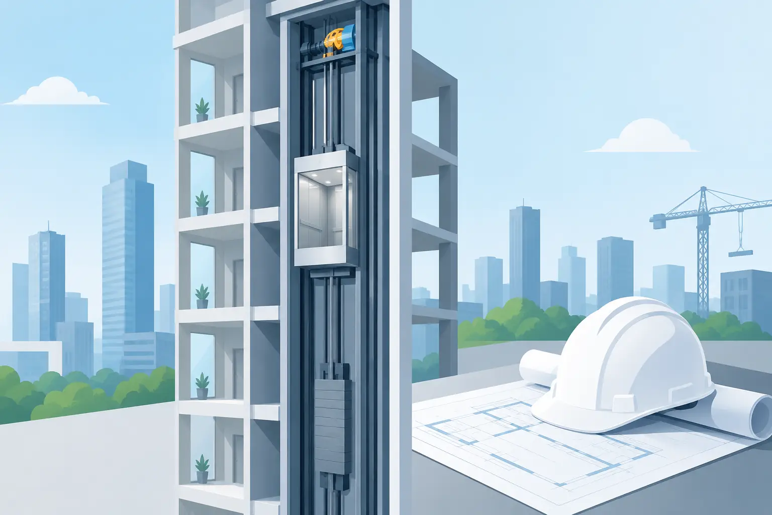
A Guide to Lift Shaft Design for New Buildings
A lift shaft is not simply a vertical opening set aside late in the build. It is a precisely coordinated part of the building that affects safety, installation timing, compliance, lift performance and future servicing. This guide to lift shaft design outlines the decisions that need to be made early, before concrete is poured or wall framing is closed in.
For builders, developers and property owners, getting the shaft right from the outset avoids costly alterations, programme delays and compromises to the lift selected for the project. The required design will vary between a home lift, passenger lift, goods lift and service lift, so the shaft should always be developed around the chosen equipment rather than a generic drawing.
Start With How the Lift Will Be Used
The most effective shaft design begins with the building’s operational needs. A low-rise residence may need a compact home lift that supports ageing in place and convenient access between levels. A commercial office, medical centre or aged care facility may require a passenger lift with higher traffic capacity, stretcher access or enhanced accessibility provisions. Industrial and retail sites may need a goods or service lift designed around trolleys, pallets, stock movement and durable finishes.
Usage determines more than car size. It influences door configuration, rated load, travel speed, number of stops, entrance widths and the equipment arrangement. For example, a through-car lift with doors on opposite sides can improve traffic flow in a busy building, but it changes the shaft layout and structural requirements. A larger car may serve tenants better, yet it also needs more shaft space and may introduce heavier imposed loads.
It pays to assess likely future use as well as current demand. Retrofitting a larger lift into an undersized shaft is rarely straightforward. Where the building has a long design life, allowing appropriate capacity from the beginning can protect the asset and reduce disruption later.
Guide to Lift Shaft Design: Core Dimensions
Every lift system has a manufacturer-specific shaft layout. This identifies the clear internal shaft width and depth, pit depth, overhead clearance, landing door openings and structural fixing locations. These dimensions are not interchangeable between lift models or suppliers.
The clear shaft dimensions must remain clear after all finishes, fire-rated linings, waterproofing details, conduits and protrusions are considered. A shaft that appears compliant on an architectural plan can become too tight once construction tolerances and wall build-ups are applied. Even a small encroachment can interfere with guide rails, car clearances or landing door installation.
The pit is the space below the lowest landing, while the overhead is the space above the top landing required for the car, equipment and safe maintenance clearances. Both are fundamental safety zones. Their exact depth and height depend on the lift type, speed, suspension arrangement and equipment selected. Do not nominate pit and overhead dimensions based on assumptions from a previous project.
Machine-room-less lifts are often a practical choice where a separate machine room is not desirable. However, machine-room-less does not mean the shaft has no equipment or access requirements. Controllers, drive components and inspection arrangements still need to be safely located, accessible and coordinated with the lift design.
Coordinate Structure Before Construction Begins
A lift shaft carries more than its own walls. It must safely accommodate guide rail forces, landing doors, buffers, lifting points and, depending on the design, machinery-related loads. The lift supplier should provide load data early so the structural engineer can design the shaft walls, slab edges, pit base and support points accordingly.
Concrete shafts are common in multi-storey commercial work because they can provide strength, fire resistance and acoustic separation. Masonry or steel-framed shaft construction may suit other applications, particularly low-rise and residential projects. The right method depends on the building structure, fire strategy, programme and available tolerances.
Accuracy matters. Shaft walls should be plumb, square and free from steps, ledges or uneven surfaces that could prevent rail brackets and doors from being fixed correctly. Builders should also allow for construction tolerances identified in the lift drawings. Correcting a shaft that is out of plumb after finishes are complete can be expensive and may delay commissioning.
The shaft should be kept clear of services that do not belong to the lift. Pipes, ductwork, cable trays and other building services can create hazards, restrict access and breach the lift supplier’s installation requirements. Coordinate penetrations carefully and only where they are approved for the shaft construction.
Plan the Pit for Safety and Drainage
The lift pit needs a level, sound and dry base. Water ingress is one of the most damaging avoidable issues in lift installations. Groundwater, stormwater runoff, failed waterproofing and leaking services can affect buffers, travelling cables, electrical components and structural fixings, while also creating a serious safety risk for technicians.
Pit waterproofing and drainage must suit the site’s ground conditions and building design. Where a sump is required, its position and details must be coordinated so it does not conflict with lift equipment. The lift pit should not be used as a building drainage point unless the solution has been specifically engineered and approved.
Safe access is equally important. Pit ladders, lighting, stop switches and other required safety provisions need to be incorporated in line with the selected system and applicable standards. These details are essential for future maintenance, fault attendance and emergency work, not optional additions at handover.
Design Landing Areas Around People and Traffic
Lift landing doors are part of the shaft system, but they also shape the experience of everyone using the building. Door width, opening direction, clear landing space and approach paths should support the people and equipment expected to use the lift.
In public-facing buildings, landing layouts need to work with accessibility requirements, circulation routes and evacuation planning. In healthcare, aged care and education settings, door widths and car dimensions may need to accommodate mobility aids, beds or supervised groups. In industrial facilities, the route from the loading area to the lift needs enough room for safely manoeuvring goods without blocking pedestrian access.
Finishes around the landing entrances should be durable and accurately set out. The sill level, wall openings and finished floor levels must align with the lift drawings. Poor coordination at this stage can result in misaligned doors, unsuitable thresholds or remedial work that affects the completed foyer or corridor.
Allow for Electrical, Fire and Building Services
Lift equipment requires a dedicated electrical supply, suitable isolation arrangements and correctly located controls. The exact requirements should be confirmed with the lift provider and electrical consultant early, including power supply characteristics, cable routes and any backup or emergency systems required for the building.
Fire and smoke requirements also need coordination with the building’s compliance strategy. Shaft enclosure ratings, landing door performance, smoke control measures and interfaces with fire services can vary according to the building classification, height and lift purpose. A lift used for normal passenger transport is not automatically designed for emergency or evacuation use.
Good communication between the architect, builder, services consultants, fire engineer and lift contractor prevents late changes. The key items to resolve before construction include:
- approved shaft dimensions, pit depth and overhead clearance;
- guide rail and structural load information;
- landing door openings and finished floor levels;
- electrical supply, lighting and communications provisions; and
- waterproofing, drainage, fire-rating and access details.
Build for Installation, Testing and Ongoing Maintenance
A lift shaft can meet nominal dimensions and still be difficult to install if site access has not been considered. Lift components, rails, doors and equipment need a practical delivery route, suitable storage area and safe method of moving materials into the building. On constrained sites, this planning can have a direct effect on programme and cost.
The shaft should be secure, weather-protected and reasonably clean before installation begins. Temporary openings, incomplete roofs, wet floors and ongoing work by other trades can place equipment at risk and interrupt installation. The builder’s programme should allow the lift contractor sufficient access for installation, testing and final adjustments without repeated trade clashes.
Maintenance access should remain part of the design conversation after practical completion. Technicians need safe access to controllers, shaft equipment and inspection points throughout the lift’s working life. Designing for serviceability supports faster fault response, safer maintenance and less downtime for occupants.
Choose Advice That Fits the Project
There is no single set of lift shaft dimensions that suits every building. The correct solution depends on the lift type, travel, traffic demand, structural system, compliance obligations and the level of future flexibility required. Early consultation is particularly valuable where space is restricted, the building has unusual geometry, or a modernisation must work within an existing shaft.
Skyrise Elevators can assist project teams with lift selection, technical drawings and practical coordination before construction decisions become difficult to change. A well-planned shaft gives the lift the space, support and access it needs to operate reliably for years, while helping the building remain safer and easier to manage.